
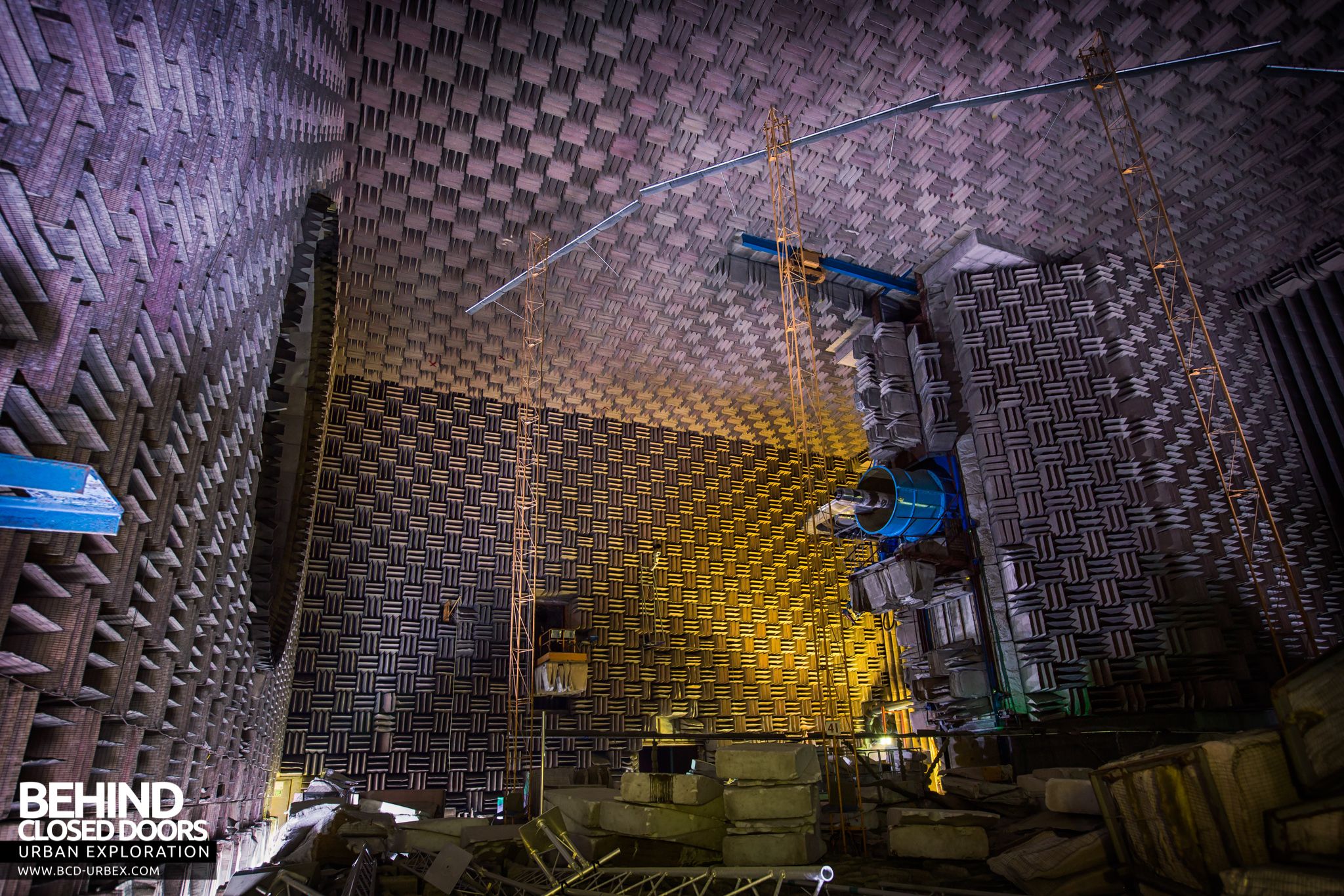
An acoustically lined, echo-free chamber that was used for noise testing of jet engines.
 Fleet, Hampshire, UK Closed, Abandoned
 The National Gas Turbine Establishment.
NGTE Pyestock – The National Gas Turbine Establishment – was a huge industrial site in Fleet, Hampshire. The site was used to test jet engines during their development and could simulate the conditions of flight in huge wind tunnels. Large scale expansion took place throughout the 50s and 60s to facilitate the much larger jet engines being developed such as those used on Concorde. The site finally closed in 2000 due to a decline in jet engine development and the advent of computer aided simulations.
The Noise Test Facility
A lot of research into noise took place at NGTE over the years, and the first anechoic chamber was built in the early 1960s. The increasing demand for quieter aircraft stimulated the more research work, and as a result a larger test facility capable of undertaking large scale noise tests on a variety of gas turbine components opened in the 1970s.
The new facility consisted of two main laboratories, fully independent of each other. These were the Absorber Rig Facility and the Anechoic Chamber facility. The Absorber Rig Facility was the first to be completed and it came into service in the summer of 1972. The Anechoic Chamber Facility was commissioned just over one year later in early 1974.
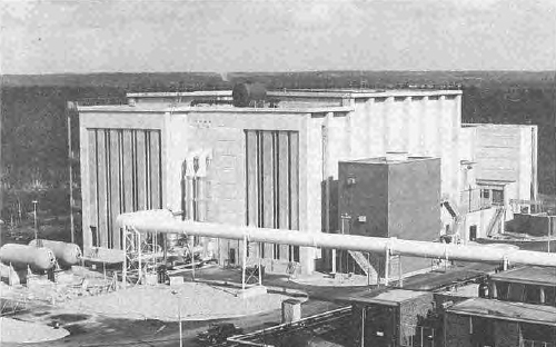
The plans below show the general layout of the building. The anechoic chamber is central with silenced air intakes to the left and the silenced exhaust duct and extraction fans to the right. The induced airflow passes through the anechoic chamber where the noise tests were conducted.

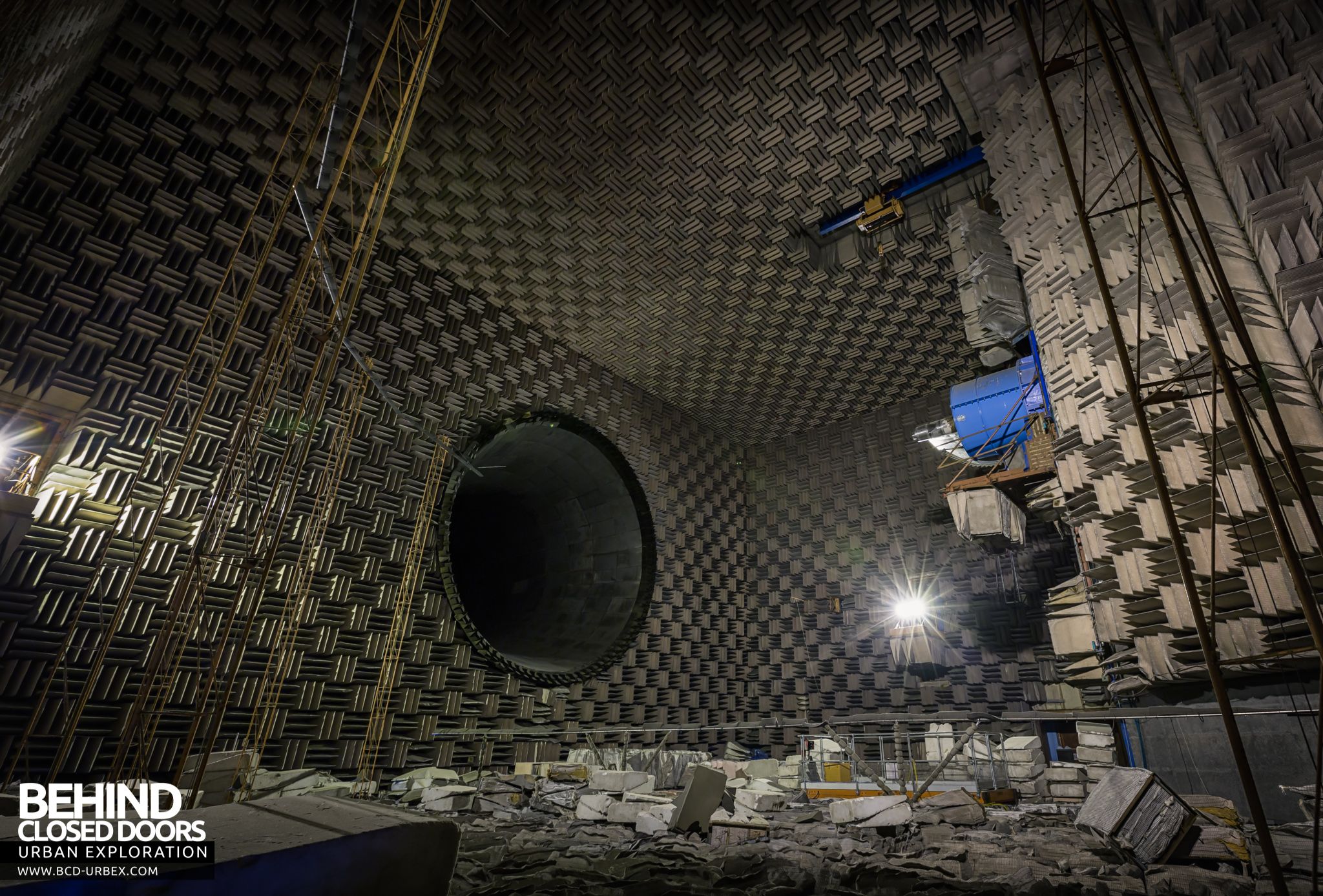
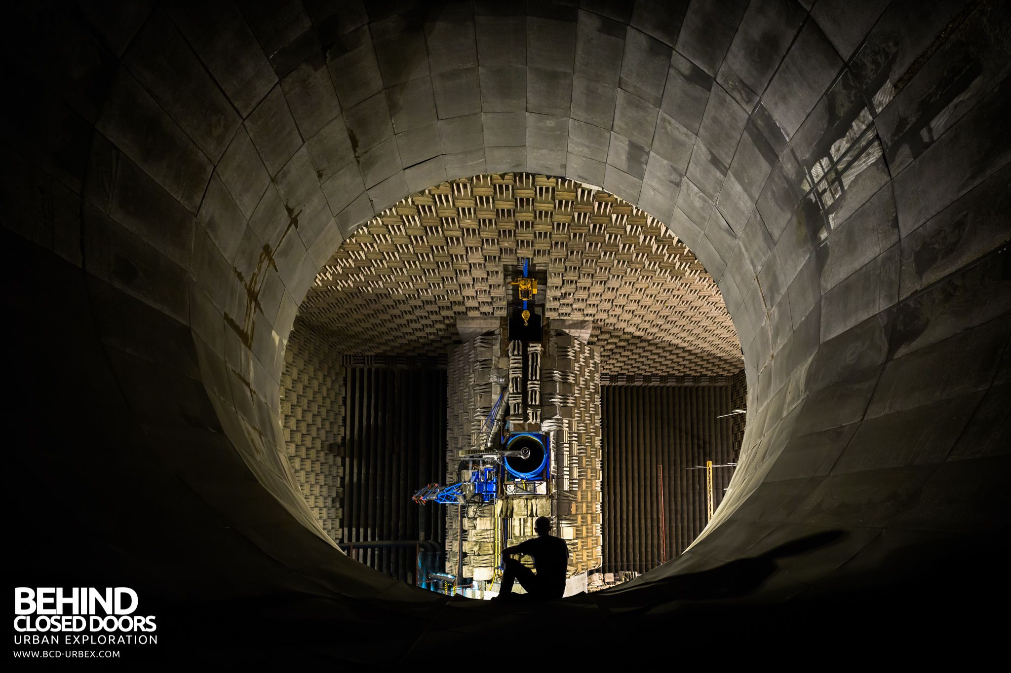
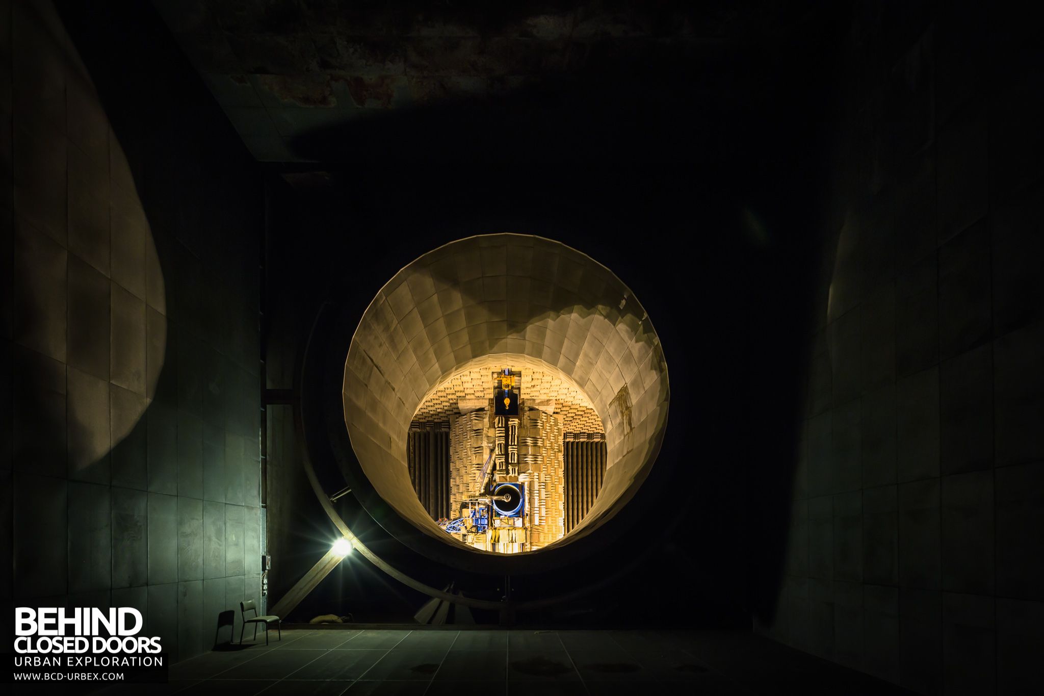
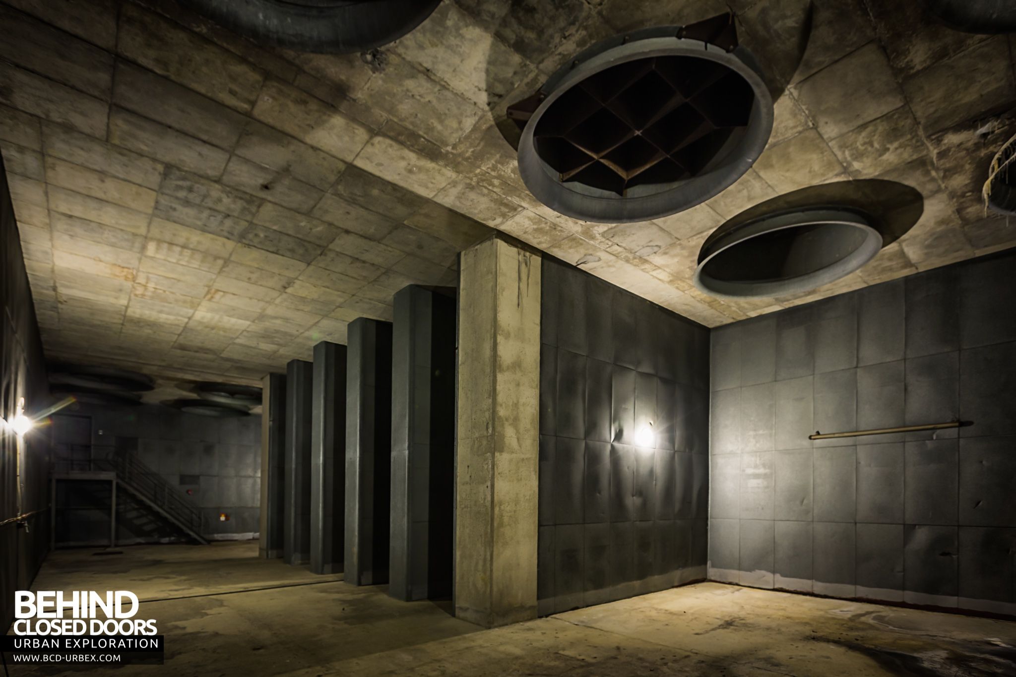
The Anechoic Facility has a 10,000 cubic metre chamber for noise testing in which the enclosed working volume has nearly zero noise reflection, thereby reproducing environmental conditions which can be compared to those in flight, and permits work to separately identify the source and direction of noise wave phenomena. The building is principally intended for the noise testing of jets, turbines and certain configurations of acoustically lined ducts.
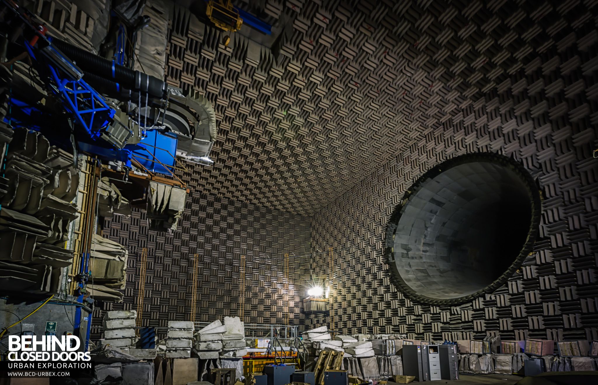
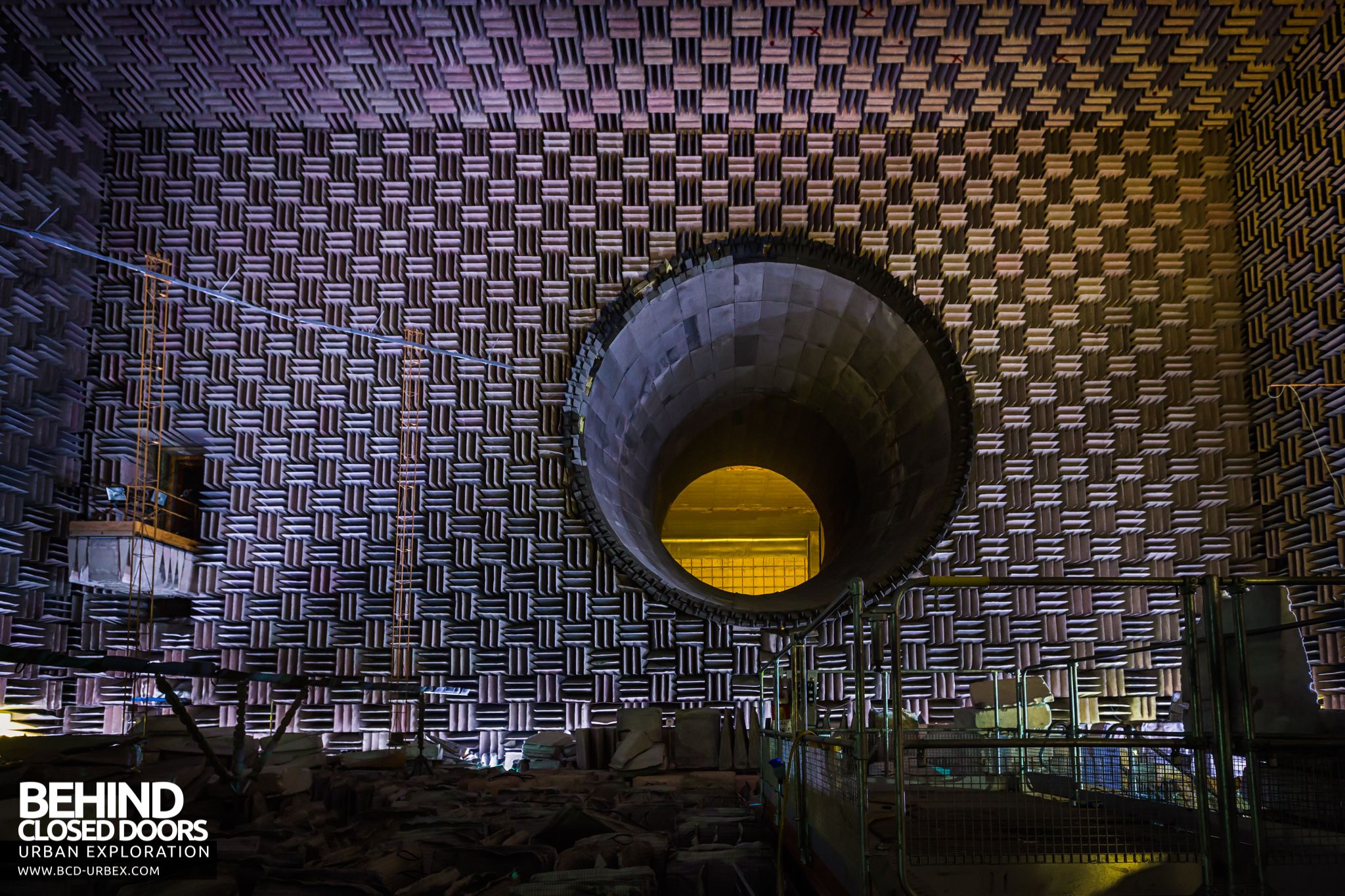
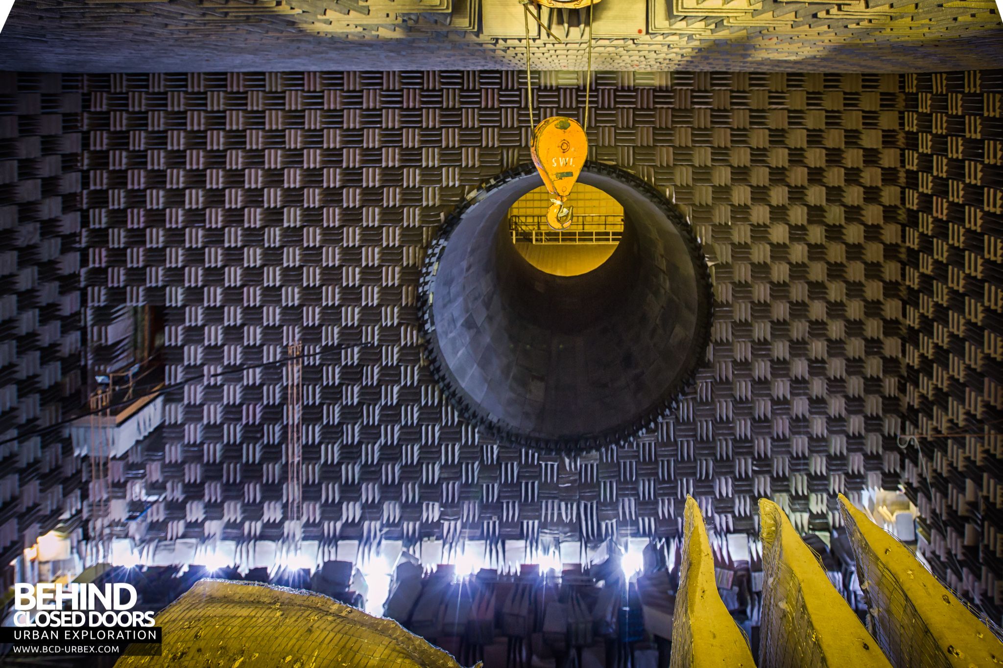
Broadly, the facility consists of an acoustically lined main test chamber 85ft wide and 46ft high with an overall length of 88ft, but which is reduced to 52ft at the working section. The jet flow from the main noise source is projected towards an acoustically lined, flared duct 28ft diameter at inlet with a 20ft diameter throat, which acts as an exhaust inducer.
Three observation galleries were positioned around the chamber. Each could be retracted to preserve the room’s anechoic properties:
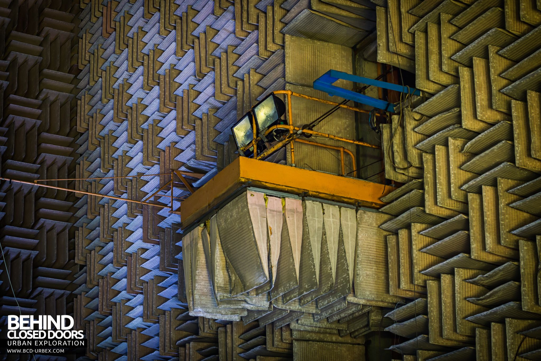
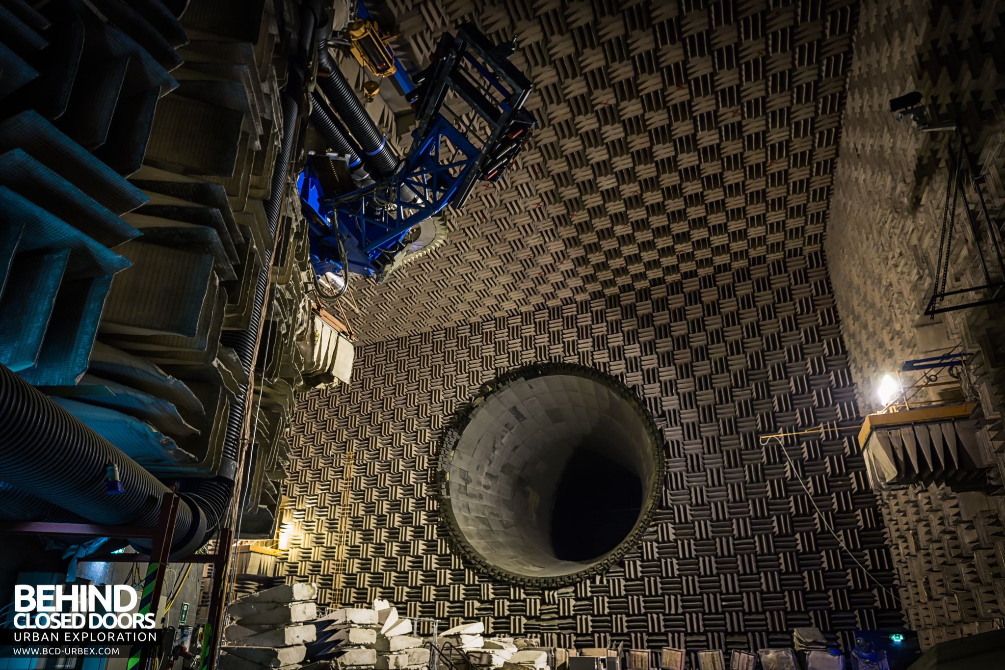
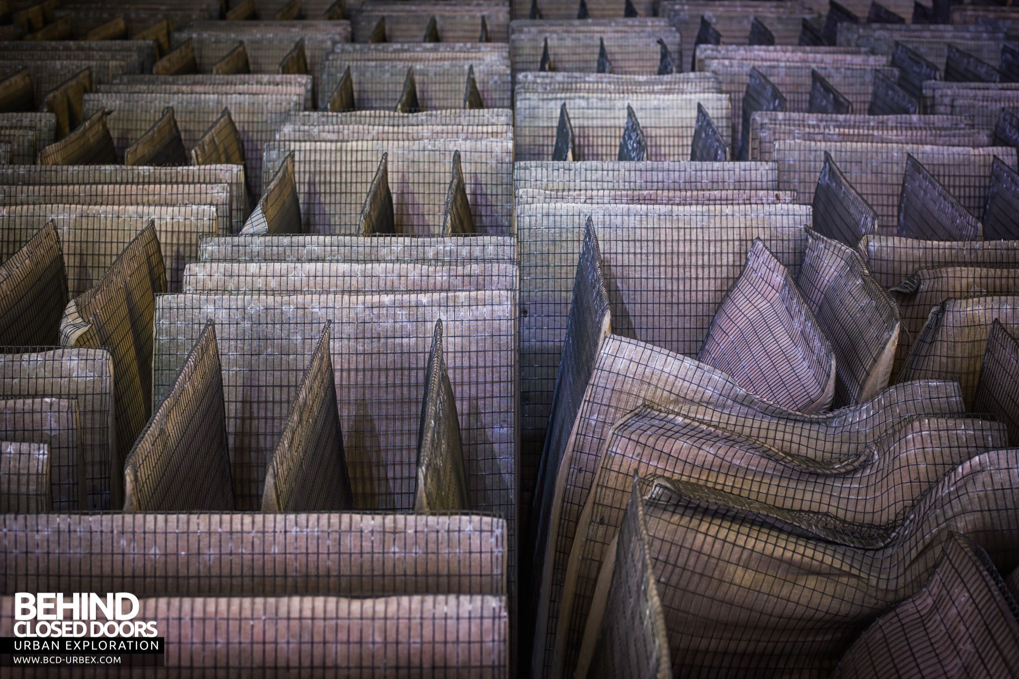
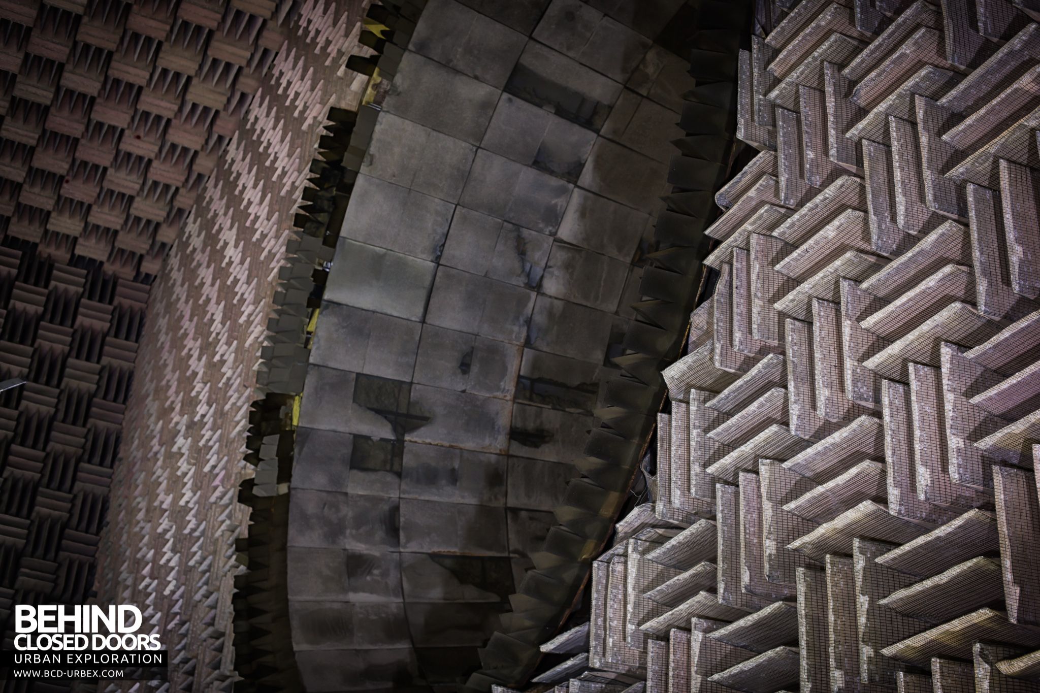
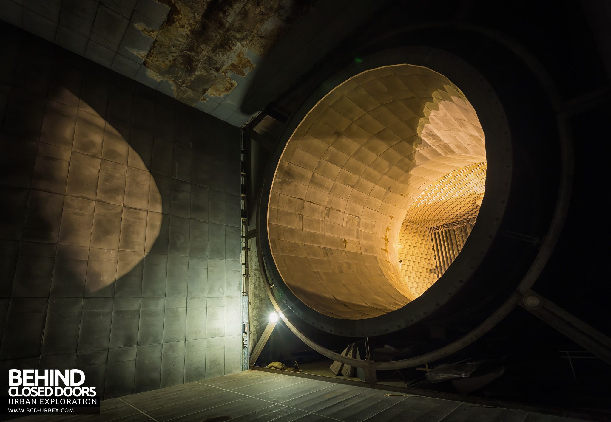
The most striking feature of the anechoic chamber itself is the sound reflecting wedges of which there are nearly 7,000 units covering the walls, ceiling and floor. Three individual wedges are mounted together on a base-frame to form each single unit 610mm square; these units are then arranged over the chamber surfaces so that each successive unit has its wedge peak edges at right angles to the neighbouring unit.
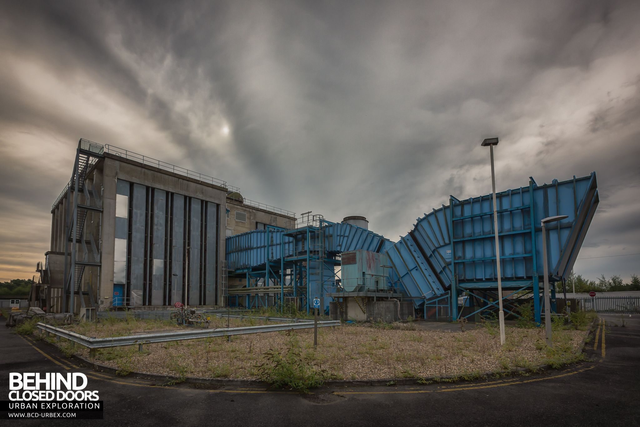
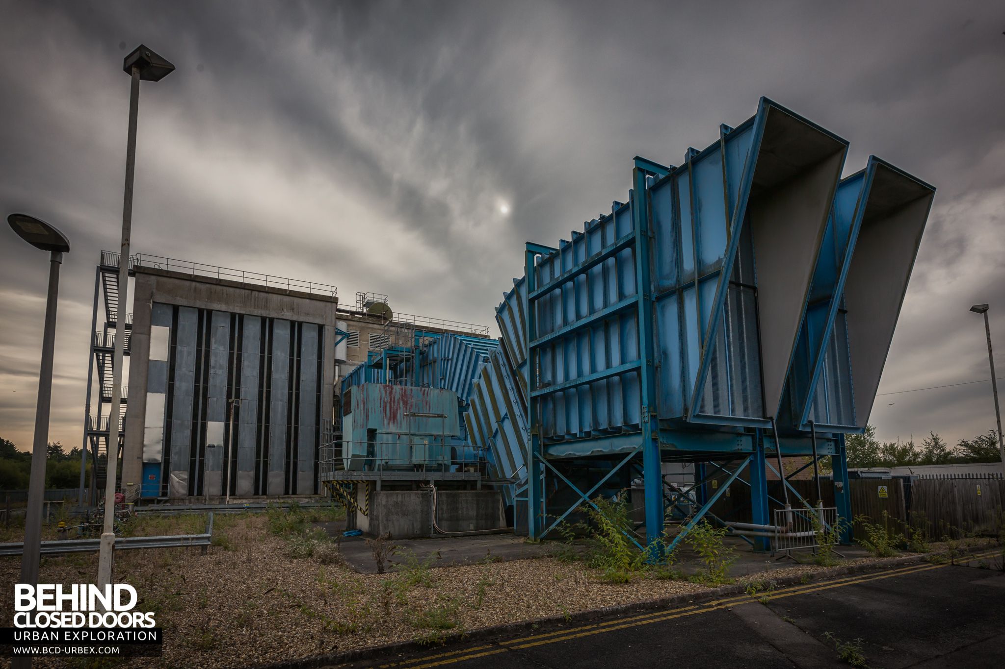
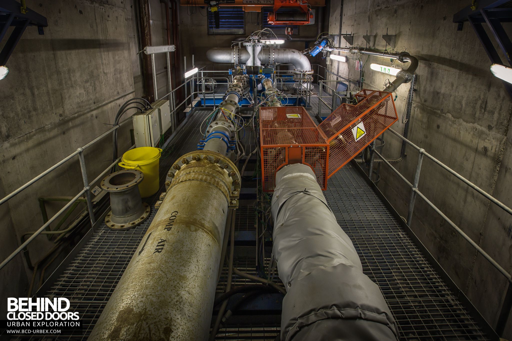
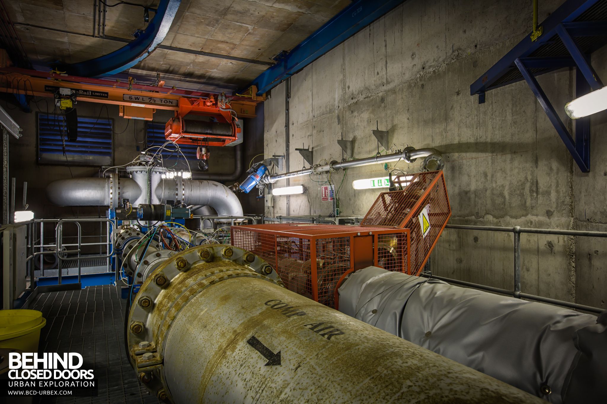
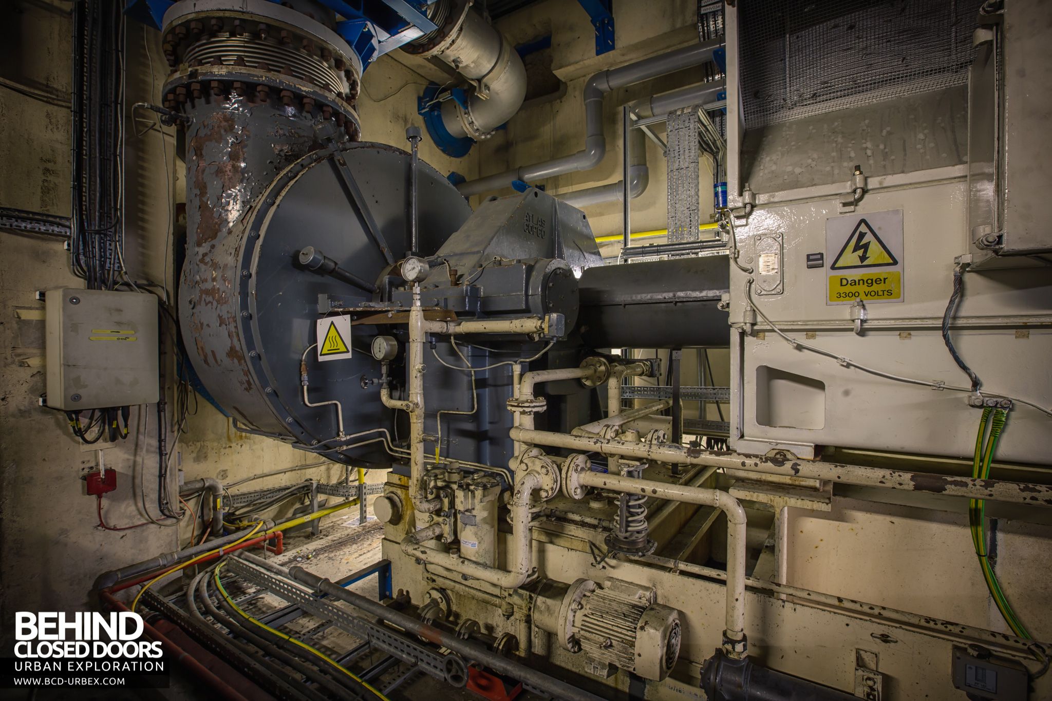
The working section was modified during refurbishment in the 1990s. A permanent nozzle was fitted through which high pressure air could be blown in using the blue external assembly shown in earlier pictures.
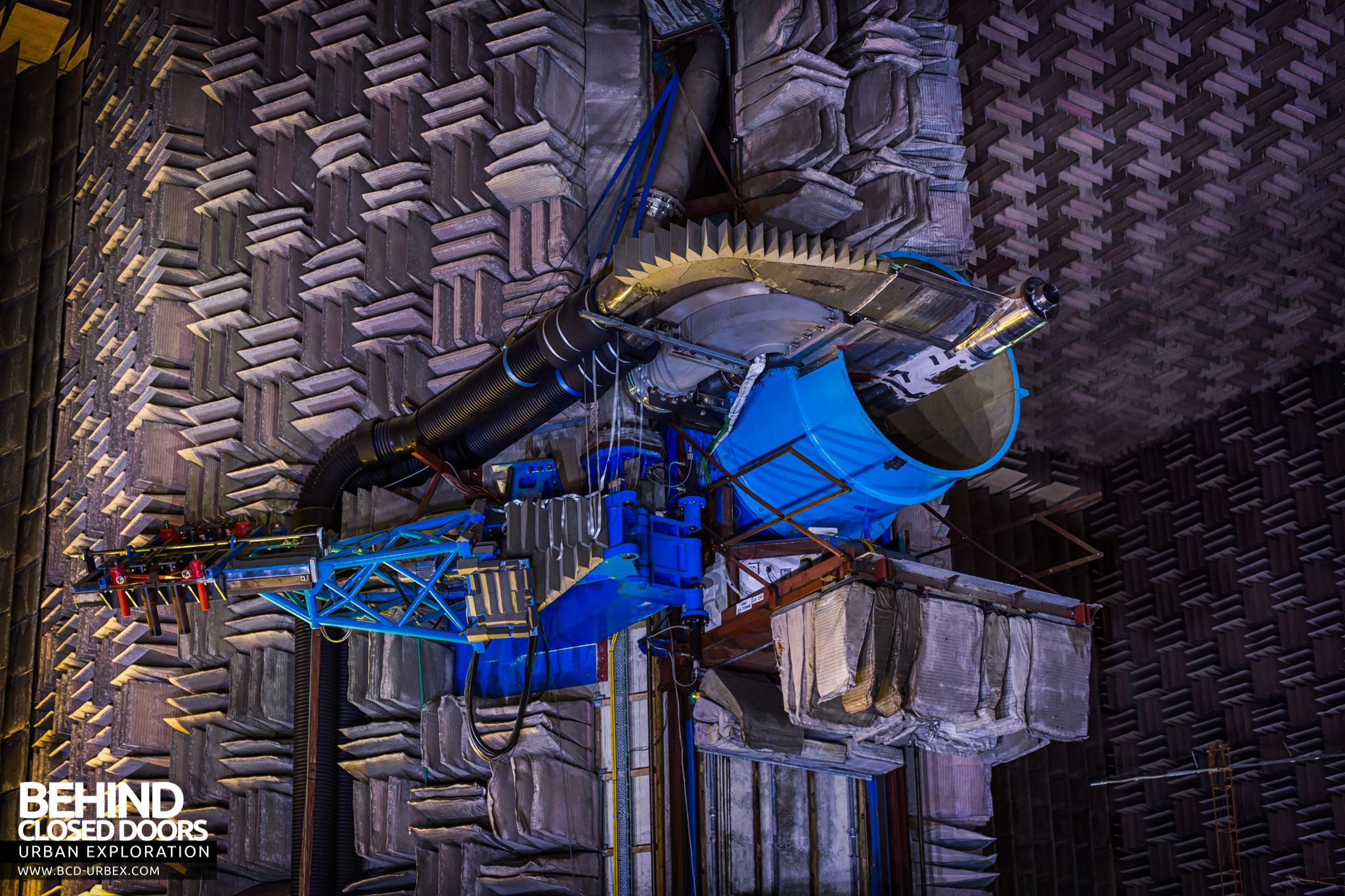
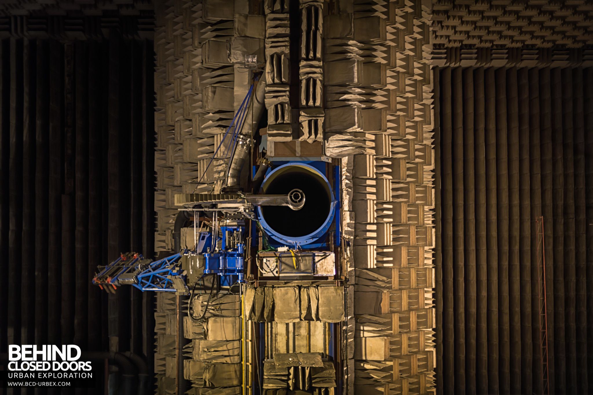
Inside the working section the area where jet engines would be positioned was replaced with a network of pipelines feeding the new nozzle.
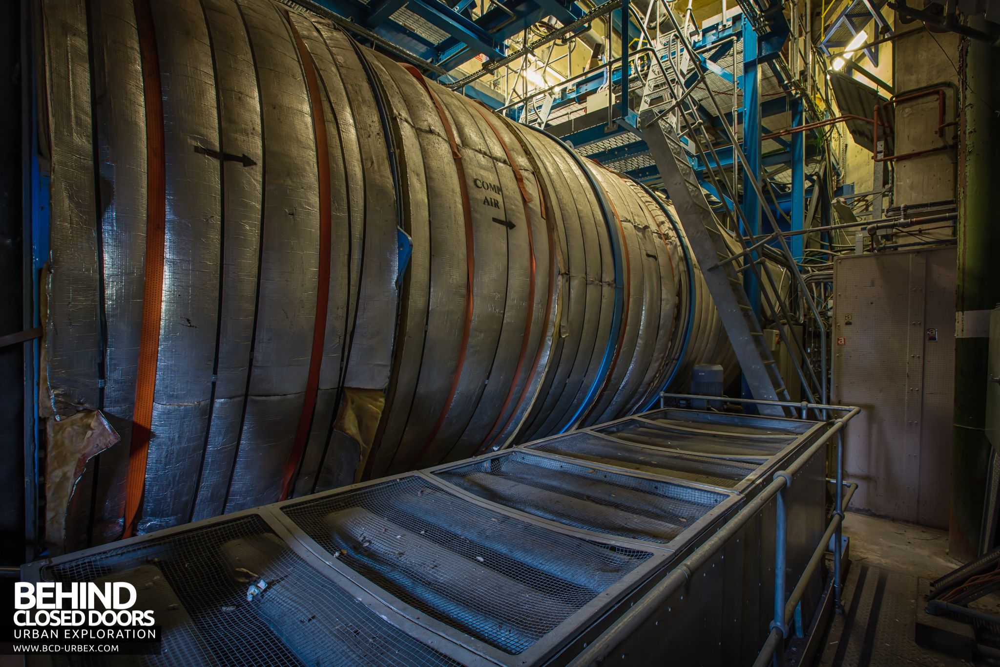
The exhaust collector was responsible for transferring the jet engine exhaust gasses and induced air from the chamber to the exhaust silencing structure behind it. It is acoustically treated around its periphery, this lagging consists of heavy density rockwool 8in thick, faced with cotton sheeting and perforated galvanised mild steel sheet. The duct itself is prefabricated from 0.25in thick steel plate and has a total length of 35ft.
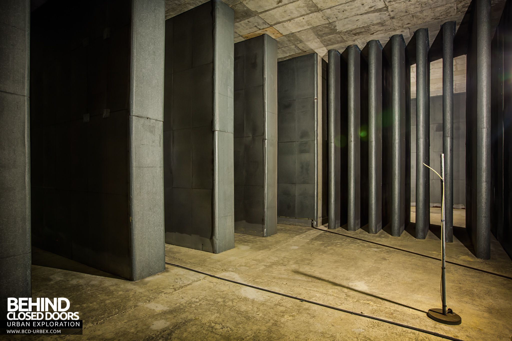
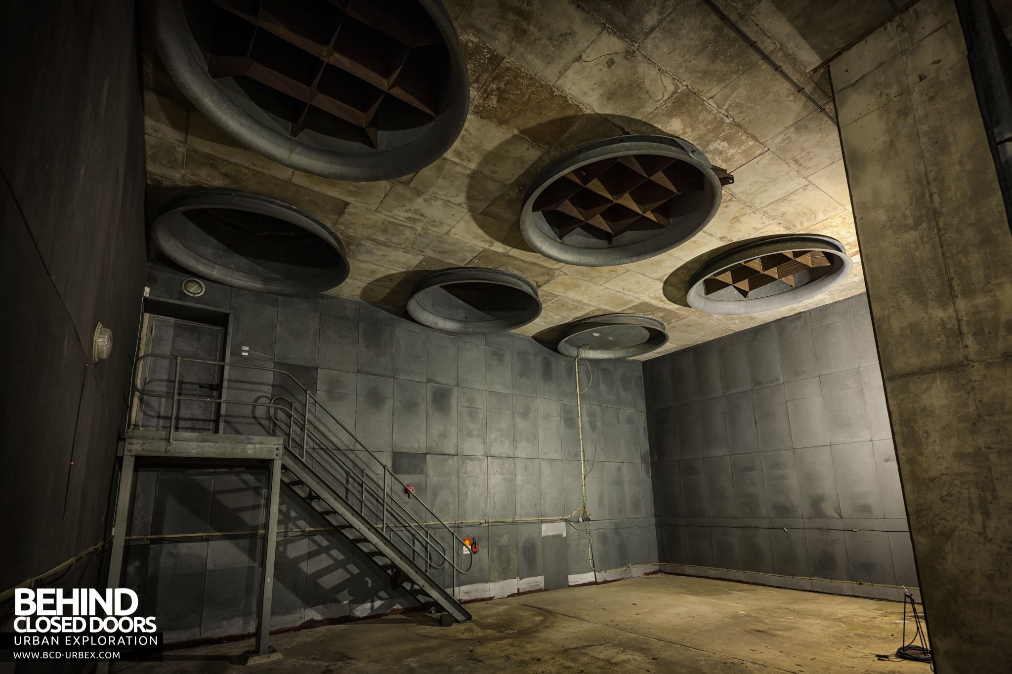
Air and exhaust gasses then pass into the exhaust silencing structure. The main features of the structure, other than the exhaust collector are the acoustically slabbed walls of the concrete ducts which reverse the flowpath, two sets of silencing exit splitters, high and low frequency, and the ten exhaust extraction fans.

The fan units themselves are double axial units having two counter-rotating six bladed fans in each pod, both with its own electric motor.
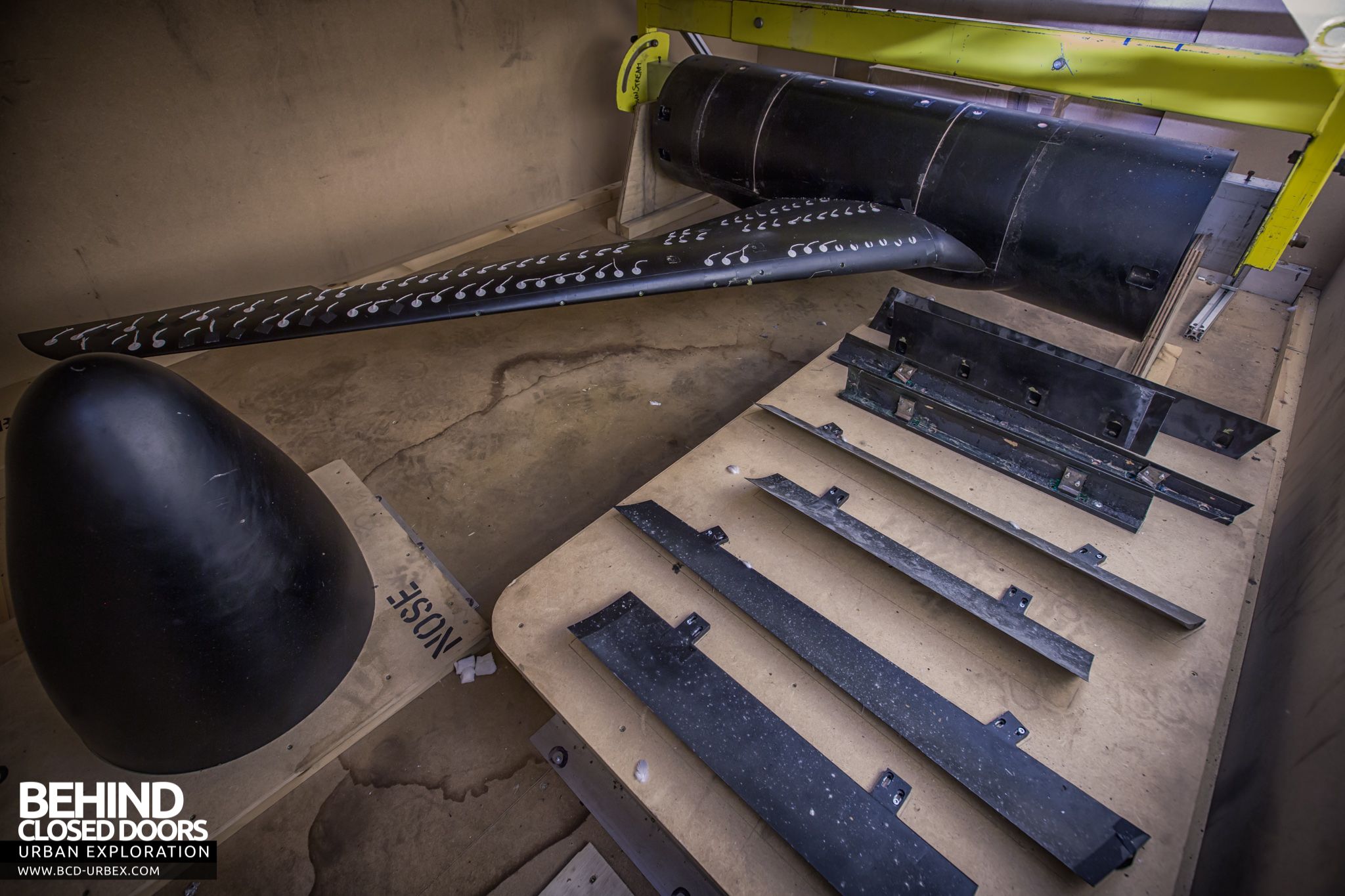
The new arrangement after the refit was particularly suited to testing ducts and propellers. One such item was found boxed up below the working section. This was possibly the last item to be tested at the site.
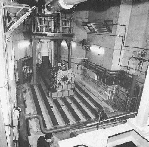
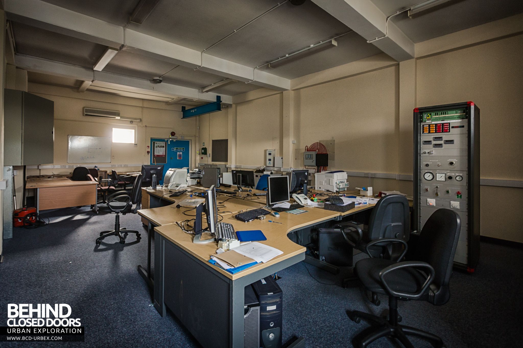
A separate building, houses the control and engineering service equipment. This building has three floors and the heavy service plant was originally installed on the lower floor with the service supplies fed to the rig room via an underground communication duct; the main control room is on the middle floor, while the upper floor houses the ancillary electronic equipment.

The control room was refitted with computerised equipment during the refurbishment in the 1990s. All that remains from the original control room is a single panel, the Plant Controller board.


very cool. cant help but imagine being stuck inside the exhaust silencing structure during operation. I assume you would not survive. Everything must be fireproof/ heat resistant too, no? For the jet engines anyways.
Is this place still there or has it been demolished?
It’s still there but kept pretty secure these days
Behind Closed Doors gutted, I’d love to be able to run around in there with my camera
Emma Oliver Me too – let me know if you are going and I will come along too!
Soo Hooper it’s being demolished right now
Behind Closed Doors looks like it’s gone now and replaced by Hartland Village.
It`s going to be demolished soon – hurry up people